
Most general building MEP standards aren’t applicable once you’re inside a commercial kitchen. The per-square-foot lighting loads, occupancy-based water demand, and standard air-change assumptions- all of the shorthand that works reliably for an office floor or a guest room break down the moment it meets a kitchen, because kitchen load isn’t driven by floor area.
It’s driven by specific pieces of equipment and its specific requirements, each with its own electrical, water, and ventilation footprint that has nothing to do with how many square meters it sits on. This is really the core of what makes Commercial Kitchen Engineering its own discipline rather than a subset of general building MEP work.
The methodology shift that follows from that is straightforward to state, if not always straightforward to apply: kitchen MEP planning is equipment-driven, calculated item by item, not space-driven. This piece walks through that bottom-up methodology across water, HVAC and ventilation, and electrical planning, where the three systems genuinely intersect rather than sitting in separate silos, and the documentation that should be driving all three calculations from the start.
Why Commercial Kitchen MEP Is a Distinct Calculation Discipline
Generic building loads scale fairly predictably with area.
Add square footage to an office floor and lighting, HVAC, and power loads scale up in a roughly linear, well-understood way.
But kitchen equipment loads don’t behave like that at all. A single combi oven or a tilting braising pan can carry a bigger electrical, water, and gas footprint than an entire adjacent office zone several times its physical size.
The practical consequence is that kitchen load calculations have to be built bottom-up from an actual equipment schedule, never estimated top-down from square footage the way a general MEP brief might approach the rest of the building. That bottom-up discipline is really the defining trait of Commercial Kitchen Engineering as its own field.
Water Planning
Cold water, hot water, and RO or purified water each need to be calculated separately, and each against a specific function rather than using the average measurements. Food prep and cooking, general cleaning, dishwashing, pot wash, hand wash, and drinking water all draw differently, at different temperatures, and at different points in the service cycle.
As industry-typical starting points, worth verifying against current equipment specifications and local code at design time rather than treated as fixed figures, water demand is often estimated in litres per cover for food prep and general wash functions, litres per wash cycle for dishwashing racks, and litres per pot for manual pot wash stations. These numbers shift with equipment brand, cycle type, and local water pressure, so they’re a starting point for sizing conversations, not a substitute for confirming against the actual equipment schedule.
Hot water temperature requirements for dishwashing equipment sit materially higher than general building hot water standards, which means dishwashing hot water can’t simply be pulled from the same supply loop serving handwash stations or general cleaning without a dedicated boost.
Water quality also becomes a real design input for imported or specialized equipment, many of which specify a maximum treated water PPM threshold to protect internal components, particularly relevant for combi ovens and specialty beverage equipment where water quality directly affects both performance and warranty terms.
Also, the wastewater output deserves to be calculated as its own and not treated as an afterthought once supply-side numbers are finalized. It feeds directly into drainage design and grease trap sizing, and getting it wrong at this stage is one of the most expensive categories of rework once concrete is poured, since moving a drain or resizing a grease trap after the slab is finished usually means demolition rather than a simple adjustment.
HVAC Planning and Ventilation for Commercial Kitchens
Exhaust hood CFM needs to be calculated per cooking station and per equipment type, never as a single flat kitchen-wide figure applied uniformly across the space. A tandoor, a wok range, and a bakery deck oven each generate heat, steam, and grease-laden air very differently, and a hood sized against an average rather than the actual equipment underneath it will underperform at exactly the stations that need it most.
The make-up air balance principle sits at the center of good HVAC Planning for any commercial kitchen. A fixed percentage of exhaust volume has to return as treated fresh air, or the kitchen ends up running at negative pressure, a condition that shows up as doors that won’t close properly and smoke or heat that doesn’t clear during service, regardless of how well the exhaust hoods themselves were specified.
Air change rate requirements also vary meaningfully by zone within the same kitchen. Storage areas, the hot kitchen, dish wash and pot wash zones with heavy vapor loads, and staff areas each carry different air-change and temperature targets, and treating the whole kitchen as one uniform HVAC zone tends to leave some areas over-conditioned and others under-conditioned at the same time.
Dual-speed exhaust and supply fan control has become a standard energy-efficiency approach worth designing in from the start, running at full capacity during active service periods and dropping to reduced capacity during low-activity periods, cutting energy cost across the life of the building without compromising performance when the kitchen actually needs full exhaust capacity.
Fire damper and fusible-link coordination at the hood-to-duct connection point is a place where HVAC and fire safety design genuinely have to be resolved jointly rather than sequentially. Getting this connection point wrong, or leaving it to be resolved late by whichever discipline gets there last, is a common source of code compliance gaps discovered at inspection rather than caught during design.
Electrical Planning
Per-equipment load calculation- kilowatts, voltage, and phase, whether single- or three-phase- has to be captured individually per item rather than estimated in aggregate. This is the same discipline that governs water and HVAC calculations, applied to electrical: bottom-up from the equipment schedule, not top-down from a rough estimate of total kitchen demand.
Panel sizing needs a deliberate future-capacity buffer built in for equipment additions or upgrades over the kitchen’s operating life, since a panel sized exactly to day-one demand leaves no room for a menu change, a new piece of equipment, or a caterer swap years down the line without a costly panel or riser retrofit.
There’s a practical distinction worth flagging that gets mishandled more often than it should: equipment supplied with a factory plug generally only needs an electrical rough-in, commonly noted as E.R. on drawings, while equipment requiring a hard-wired connection needs a direct, electrical-only connection, commonly noted as E.O. This classification affects rough-in planning significantly, since getting it wrong means either an unused outlet sitting where a hard-wired connection was actually needed, or the reverse.
Wash areas carry their own electrical requirements given the wet environment they operate in, specifically weatherproof and splash-proof switch and socket ratings appropriate to constant exposure to water and cleaning chemicals, a requirement that’s easy to overlook if electrical planning is drawn from a general building standard rather than a kitchen-specific one.
Electrical also has to coordinate directly with gas planning wherever dual-fuel equipment is involved, since interlock and shutoff requirements between the two systems need to be resolved together rather than designed by two disciplines working from separate assumptions about how the equipment actually operates.
Where the Three Systems Actually Intersect
This is really the section worth paying closest attention to, because it’s where a single design decision routinely affects more than one system at once, and where sequential design, one discipline finishing before the next one starts, creates most of the rework that shows up later in a project.
Honestly, an exhaust hood placement affects both HVAC routing and fire suppression system design simultaneously, since moving a hood after fire suppression has already been specified against its original position forces a redesign of both systems together, not just the one that technically moved.
Floor drain and drain trough placement affects electrical socket and switch height requirements, since code-driven clearance from water sources constrains where electrical fixtures can sit, which means drainage decisions made without electrical input can quietly force an electrical redesign later. And HVAC-driven equipment spacing and clearance requirements affect where water rough-in points can actually be located, since a water point placed without accounting for required equipment clearance may end up trapped behind a piece of equipment it was meant to serve.
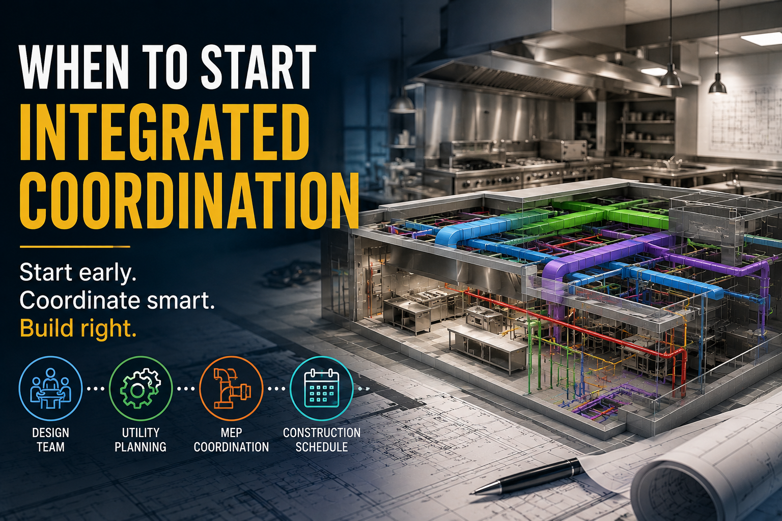
The point underlying all three examples is the same one: these aren’t three independent disciplines that happen to share a room. A change in one system’s design routinely forces a change in the other two, which is exactly why sequential MEP design creates rework that parallel, coordinated design avoids. Genuine MEP Coordination on a kitchen project means these intersection points get resolved jointly, while the design is still flexible, not discovered independently by each discipline once drawings are already substantially fixed.
| Intersection Point | Systems Involved | What Happens If Resolved Sequentially |
| Exhaust hood placement | HVAC, fire suppression | Suppression system redesign if hood moves later |
| Floor drain and trough placement | Drainage, electrical | Electrical fixtures forced into non-compliant clearance |
| Equipment spacing and clearance | HVAC, water rough-in | Water points trapped behind installed equipment |
| Hood-to-duct connection | HVAC, fire safety | Fire damper coordination gap caught at inspection |
| Dual-fuel equipment | Electrical, gas | Interlock and shutoff mismatch discovered on commissioning |
Common Technical Errors Worth Watching For
A handful of errors show up repeatedly across kitchen MEP projects, regardless of project scale or building type.
Sizing water, electrical, or HVAC from generic per-square-foot building standards instead of an actual equipment schedule is the most common root cause, and nearly every other error on this list traces back to it in some form.
Treating exhaust and make-up air as two separately-sized systems, rather than one balanced system that has to work together, produces a kitchen that looks correctly specified on paper and runs at negative pressure in practice.
Applying a flat diversity factor uniformly across all equipment, rather than accounting for genuine variation in simultaneous-use patterns, since not every piece of equipment runs at full load at the same moment, tends to produce panels and utility feeds that are either needlessly oversized or quietly undersized at actual peak demand. And omitting a future-capacity buffer entirely leaves no room for equipment upgrades without a full panel or riser retrofit, turning a routine future upgrade into a disruptive infrastructure project.
The Documentation That Should Drive These Calculations
All of this points toward a single document worth treating as the shared source of truth across every discipline involved: the Kitchen Mechanical Data Sheet, or KMDS. This is a single technical document capturing water, electrical, gas, and HVAC requirements per equipment item, built directly from the equipment schedule rather than compiled after the fact from separate discipline-specific assumptions.
This reinforces a sequencing principle that applies across every stage of kitchen planning: the equipment schedule needs to be locked, or at minimum reasonably firm, before MEP rough-in drawings are finalized, not the other way around. Attempting good Commercial Kitchen Layout Design without a firm equipment schedule in hand is effectively designing rough-ins against a moving target, and reconciling the gap later is always more expensive than getting the sequence right from the start.
The KMDS is really the technical artifact that makes genuine integrated coordination possible in practice, rather than just an aspiration discussed in a project kickoff meeting. It’s the document that lets water, HVAC, and electrical planning happen in parallel, informed by the same underlying numbers, instead of three disciplines working from three separate sets of assumptions and reconciling the differences during construction.
One Interdependent System, Not Three Checklists
Water, HVAC, and electrical planning for a commercial kitchen aren’t three separate checklists to work through independently. They’re one interdependent system that has to be calculated and coordinated together, with each discipline’s decisions genuinely constraining the other two at multiple points throughout the design.
For architects and MEP consultants, the practical implication is mostly about sequencing: request the equipment schedule and KMDS-level detail early in the project, rather than designing rough-ins against assumptions and reconciling the gaps later once they’re expensive to fix.
Real MEP Coordination on a kitchen project starts with that single request. For projects where foodservice MEP complexity exceeds typical general building MEP experience, this is exactly the kind of coordination worth bringing in a technical collaborator for, not as a vendor relationship, but as a peer resource for the specific calculations and coordination points this piece has walked through.